Impact Factor ISSN: 1837-9664

 Global reach, higher impact
J Cancer 2014; 5(3):192-202. doi:10.7150/jca.8395 This issue Cite
Research Paper
Radiation Exposure of Patients by Cone Beam CT during Endobronchial Navigation - A Phantom Study
Wolfgang Hohenforst-Schmidt1, Rosemarie Banckwitz2, Paul Zarogoulidis3,4 ![]() , Thomas Vogl5, Kaid Darwiche4, Eugene Goldberg6, Haidong Huang7,8, Michael Simoff8, Qiang Li7, Robert Browning9, Lutz Freitag4, J Francis Turner10, Patrick Le Pivert11, Lonny Yarmus12, Konstantinos Zarogoulidis3, Johannes Brachmann1
, Thomas Vogl5, Kaid Darwiche4, Eugene Goldberg6, Haidong Huang7,8, Michael Simoff8, Qiang Li7, Robert Browning9, Lutz Freitag4, J Francis Turner10, Patrick Le Pivert11, Lonny Yarmus12, Konstantinos Zarogoulidis3, Johannes Brachmann1
1. II Medical Clinic, Coburg Hospital, University of Wuerzburg, Coburg, Germany;
2. Siemens AG Healthcare Sector, Forchheim, Germany;
3. Pulmonary Department-Oncology Unit, G Papanikolaou General Hospital, Aristotle University of Thessaloniki, Thessaloniki, Greece;
4. Department of Interventional Pneumology, Ruhrlandklinik, West German Lung Center, University Hospital, University Duisburg-Essen, Essen, Germany;
5. Department of Diagnostic and Interventional Radiology, Goethe University of Frankfurt, Frankfurt, Germany;
6. Biomaterials Science and Engineering, Department of Materials Science and Engineering, University of Florida, FL, USA;
7. Department of Respiratory Diseases, Changhai Hospital/First Affiliated Hospital of the Second Military Medical University, Shanghai, People's Republic of China;
8. Bronchoscopy and Interventional Pulmonology, Pulmonary and Critical Care Medicine, Henry Ford Hospital, Wayne State University, School of Medicine, MI, USA;
9. Pulmonary and Critical Care Medicine, Interventional Pulmonology, National Naval Medical Center, Walter Reed Army Medical Center, Bethesda, MD, USA;
10. Pulmonary Medicine, University of Nevada School of Medicine, National Supercomputing Center for Energy and the Environment University of Nevada, Las Vegas, NV, USA;
11. Interventional Drug Delivery Systems and Strategies (ID2S2), Medical Cryogenics, Jupiter, FL, USA;
12. Division of Pulmonary and Critical Care Medicine, Sheikh Zayed Cardiovascular & Critical Care Tower, Johns Hopkins University, Baltimore, U.S.A.
Received 2013-12-19; Accepted 2014-1-23; Published 2014-2-6
Abstract
Rationale: Cone Beam Computed Tomography imaging has become increasingly important in many fields of interventional therapies. Objective: Lung navigation study which is an uncommon soft tissue approach. Methods: As no effective organ radiation dose levels were available for this kind of Cone Beam Computed Tomography application we simulated in our DynaCT (Siemens AG, Forchheim, Germany) suite 2 measurements including 3D acquisition and again for 3D acquisition and 4 endobronchial navigation maneuvers under fluoroscopy towards a nodule after the 8th segmentation in the right upper lobe over a total period of 20 minutes (min). These figures reflect the average complexity and time in our experience. We hereby describe the first time the exact protocol of lung navigation by a Cone Beam Computed Tomography approach. Measurement: The hereby first time measured body radiation doses in that approach showed very promising numbers between 0,98-1,15mSv giving specific lung radiation doses of 0,42-0,38 mSv. Main results: These figures are comparable or even better to other lung navigation systems. Cone Beam Computed Tomography offers some unique features for lung interventionists as a realtime 1-step navigation system in an open structure feasible for endobronchial and transcutaneous approach. Conclusions: Due to this low level of radiation exposure Cone Beam Computed Tomography is expected to attract interventionists interested in using and guiding endobronchial or transcutaneous ablative procedures to peripheral endobronchial and other lung lesions.
Keywords: Dyna CT, lung cancer, diagnosis.
Introduction
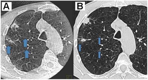
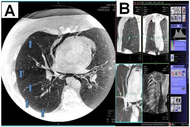
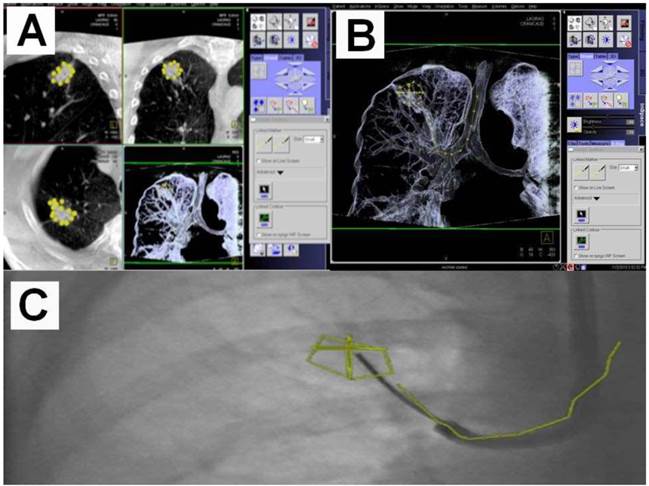
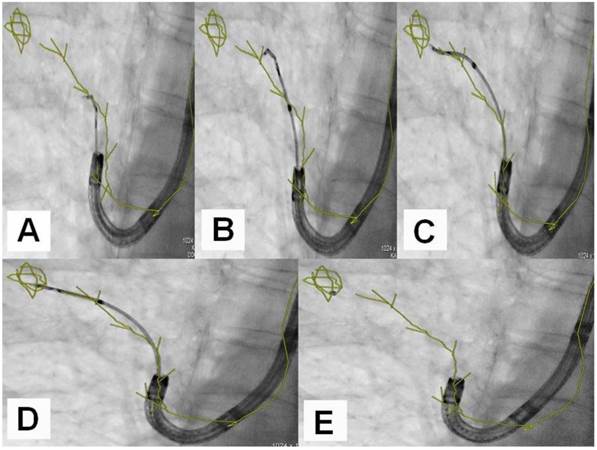
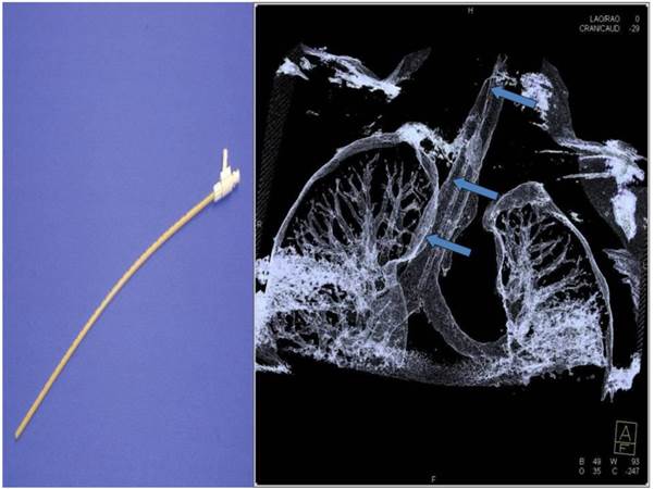
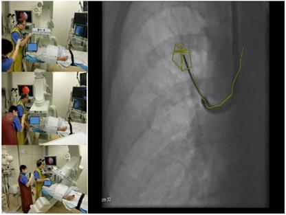
Cone Beam Computed Tomography (CBCT) imaging has become increasingly important during lung navigated interventions, demonstrating a fact that is correlated with modern endoscopic and image-guided diagnostic and/or therapeutic modalities addressing thoracic malignancies.[1-11] First reports on medical navigation during thoracic surgical procedures such as from the SHG Hospital Voelklingen, Germany and University Hospital, Saga, Japan (Customer Magazine AXIOM Innovations November, 2012) paved the way to advanced thoracic operative theaters in that they allow multimodal interventional approaches. However CBCT navigation carries an additional radiation exposure to patient and operator, which has not been measured or published for lung procedures to this day. Modern CBCT configurations allow the standard 2-dimensional (2D) projection functionality like fluoroscopy as well as volumetric computed tomography (CT) capabilities within the interventional suite. For acquisition of the 3-dimensional (3D) dataset the C-arm of CBCT needs to rotate by at least 200° (180° plus fan angle) around the target that has to remain stationary during acquisition.[12] For our lung image acquisition we use the 5 seconds (s) run with 248 single 2D-projections with a 30cm*40cm head. Our protocol is providing sufficient image quality for clearly displaying the bronchial structures as well as the target itself. (Figure 1) These data are sent automatically to a workstation where the reconstruction is completed within less than 15s. At the workstation the target itself as well as the path within the bronchial tree are identified and marked with manual annotation tools (Siemens iguide toolbox). Afterwards these markers are projected and overlaid to the fluoroscopic image. (Figure 2) This technique allows the physician to match his instruments to the overlay and in consequence navigate correctly to the (sometimes fluoroscopy-invisible) target. The major limitation of this technique is significantly poorer image quality if there is target motion during 3D acquisition. For eliminating this factor the absence of spontaneous respiration is mandatory - the patient has to be put into apnea. The connected jet ventilation system (TwinStream, Carl Reiner, and Austria) is maintaining the inspiration phase during acquisition and navigation process. This leads to an accurate match between the 3D dataset and the fluoroscopic image. At the same time maintained inspiratory ventilator set-up with high inspiratory pressures (e.g. at least over 2,5bar) over e.g. 12s hyperinflates the lung. This offers good visualization of bronchioli smaller 3mm in diameter after the 7th-8th segmentation. (Figure 3, 4) When used in normofrequent jet-ventilation (e.g. jet-ventilation with respiratory frequency (RF) 80/min with inspiration-exspiration ratio (I: E) of 1:1,5) standard inspiratory working pressures (SIWP) initially are set up along the weight of a patient: (SIWP) (bar) = (weight (kg)*0,015) with a fractional inspiratory oxygen concentration (FIO2) 0,8-1. To perform 3D data acquisition under hyperinflation it is necessary to change the set-up of the ventilator to RF 2/min with an I: E 3:1 giving at least 15s of maintained hyperinflation without any movement: During this period there is perfect alignment between the virtual anatomy derived from the 3D data acquisition overlaid in fluoro imaging and the real anatomy. To reach the optimal hyperinflation the SIWP is elevated in steps of 0,5bar until a peak inspiratory pressure (PIP) measured at the tip of the double lumen jet-catheter (Acutronic, Medical Systems, Switzerland) reaches 40mbar. (Figure 5) The positioning of the jet-catheter is performed by seldinger technique with use of a pulmonary jag-wire (Boston Scientific, USA).
A) DynaCT with a bit of motion artefact, B) Right: HRCT 1mm nearly same level; slices same patient (2 adeno-carcinomas: *) Showing the same nice details (arrows at the same position indication bronchioli of 2mm and less).
A) DynaCT with carcinoid*Arrows indicating small bronchioli subpleural. B) Right: iguide toolbox with the same dataset before annotation of the path and target volume.
A) Dotting the pathway in the 3 standard axis, B) Segmentation and dotting of the SPN in the 3 standard axis, C) Overlay in fluoroscopy (different patients).
An example of navigation up to a SPN after the 8th segmentation (counted from the main carina).
Jet-catheter inserted in trachea in DynaCT (arrows).
Materials and Methods for radiation exposure measurements
The male Alderson-Rando phantom (The Phantom RANDO®, Alderson Research Laboratories Inc., Stamford, CT, USA) (mARp) is an anthropomorphic phantom which can be equipped with dosimeters. (Figure 6.) It consists of a human skeleton which is embedded in a rubber composition with isocyanate having a specific density of 0.985 g/cm ³ along with absorption and scattering properties to X-rays equivalent to those of the human tissue.
The male Rando Alderson phantom 3edge angulations with 3 different views at least 30 degrees different to each other and with one oblique view.
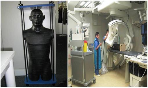
The height of the limb-less body phantom is 173 cm, its weight amounts 73.5 kg. The sagittal diameter of the abdomen measures 22 cm. The phantom can be disassembled into 2.5 cm thick, axial slices. Each layer is provided with holes meant for holding dosimeters. These dosimeters are thermoluminescense detectors (TLD). These detectors are based on the emission of thermoluminscence (TL) on heating of previously exposed crystalline materials. The intensity of the emitted TL is a function of the dose deposited in the material, and can therefore be used for dosimetry.
Calibration of TLD
In TLD with the same time-radiation history i.e. always irradiated, analyzed and regenerated together at the same time, the change in the calibration factor is approximately equal.
Therefore, the TLDs are summarized in batches which always pass together through a measurement cycle. A batch is always divided into two fractions during a measurement. The first fraction (F1) is subjected to a calibration irradiation at a defined dose (1 Gy) to determine the change in the calibration factor. This change of calibration factor can be applied to the second fraction (F2) which is used for the actual measurement of the radiation dose.
As a TLD for the organ dose measurements serves Lithium-Fluorid-thermoluminescence dosimeters (The Harshaw Chemical Company, Chrystal and Electronics Products Department, Solon, Ohio, USA) (TLD-100 rods, 1 x 1 x 6 mm). The locations are selected on the basis of a CT atlas. Three TLD rods were packed in plexiglass tube and then inserted into the corresponding holes of the respective layer of the mARp. For dose measurements with the mARp 150 TLDs were fitted to 43 different measuring points.
TLD-Reader
The TLD rods were stabilized C ("pre-annealing") and analysed in the next hours following the investigation for 10min at 100°. The TLD reader used is an analyzer type Harshaw. For these analyses the TLDs are placed in an evaluation unit which provides at the same time for heating and for transmitted light detection during the heating process. For light detection photomultiplier (PM) are used. The electric current generated by transmitted light during the heating process is proportional to the amount of light emitted from the TLD. Before each measurement a current measurement under dark conditions is carried out to ensure a constant PM sensitivity. The dosimeters are heated in 20 s with a linear increase in temperature to 270°C. The measured values are adjusted by the background radiation, which is determined by fraction F1 of each TLD-rod batch. Each organ dose results from the average of the adjusted data from the three TLD rods per measurement point. A backscatter correction of the measured values for the dose is performed. From the different measured values of organ doses finally the effective patient dose is calculated.
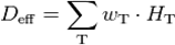
Calculation of the effective patient dose
The effective dose (otherwise known as the effective dose equivalent) is a measure of radiation exposure of humans. To calculate the effective dose (Deff) the organ doses (HT) are multiplied by the tissue weighting factor (wT) of each organ (T). The sum of such weighted organ doses results in the effective (whole body) dose in Sievert (Sv):
The tissue weighting factors were used by us in accordance with the current recommendations of the International Commission on Radiological Protection (IRCP). [13] The dose-area product has been stored for the entire investigation.
Dose-Area product (DAP)
The DAP was recorded using a panel attached to the ionization measurement chamber and by a reader (Diamentor M3, PTW, Freiburg, Germany) the value appeared in "cGycm²".
It is calculated by multiplying the ionization in air (air kerma [cGy]) in the measurement chamber with the irradiated area [cm²]. The DAP and the fluoroscopy time were recorded separately for the above mentioned subsequent simulated investigation over 20min. Furthermore, the kV and mA values were recorded.
Our standard protocol of specific jet-ventilation with deep sedation in complete apnea for the purpose of CBCT guided endobronchial navigation consists of the following steps:
- Seldinger-technique for jet-catheter positioning in the middle part of the trachea.
- Initiation of sedation protocol to achieve very low frequency of spontaneous breathing near apnea with remifentanil- (0,05ug/kg/min) and propofol-perfusors (4mg/kg/h). For definite apnea during data acquisition we used additional boli of 50mg propofol. In case of low blood pressure we applied saline 0,9% and sometimes akrinor (Ratiopharm, Germany; 2ml consists of cafedrinhydrochlorid 200mg and theodrenalinhydrochlorid 10mg as main drugs), in case of low heart frequency less than 50/min we applied atropine (B. Braun, Germany; 0,5mg/ml).
- Bronchoscopic control of the jet-catheter position after nasal fixation to avoid direct objection against any endoluminal obstacle and introduction of an oral Guedel tube to keep pharynx and mouth open.
- Application of the above mentioned low frequency inversed ratio jet-catheter set-up with FIO2 100% and uptitration of the SIWP up to a PIP of 40mbar. The maximum allowed SIWP is 3,5bar. By this means we achieve maximal tolerable hyperinfiltration.
- Establishing complete apnea by the use of additional propofol boli for data acquisition under constant hyperinflation with CBCT.
- Annotation of the path and the target with the Siemens toolbox and overlay of this 3D-information in the fluoroscopy image.
- In a situation of navigational decision the same ventilator set-up as during data acquisition has to be applied in order to guarantee perfect alignment of the virtual path and target volume with natural anatomy.
- Navigation control is achieved by the so called 3-edges-angulation during this period of perfect alignment. From a posterior-anterior position of the DynaCT-head one has to angulate thirty degrees lateral, then follow with another angulation of thirty degrees caudal or cranial and finally angulate thirty degrees medial. (Figure 7.) The examiner has to compare these 3 views of the used endobronchial probe under fluoroscopy with the virtual anatomy overlaid in the fluoroscopy image: If we observe that the probe in all views stays in the virtual path segmentation or the target volume we can conclude that it has reached the desired anatomical position endothoracically. The number of 3-edges angulations needed depends on the complexity of the path and the endoluminal entry into the target. During the examination time when no navigational decision is needed we apply normofrequent jet-ventilation (e.g. RF 80/min; I: E 1:1, 5; SIWP in regards to blood gases).
- Biopsy is performed within the second of the manual stop of the ventilator set-up to avoid peripheral pneumothorax under hyperinflation. Repeated biopsies are done without additional 3-edges-angulations via an applied sheath which was used with first biopsy put over the instrument.
3edge angulations with 3 different views at least 30 degrees different to each other and with one oblique view.
Results
With the following standard program on our ceiling-mounted Artis Zee we found a whole body effective radiation dose of 0,98mSv under CBCT data acquisition for a SPN in the RUL. Adding 4 maneuvers of endobronchial lung navigation towards a SPN after the 8th segmentation in the RUL over 20min this dose increased to 1,15mSv for acquisition and navigation. (Tables 1, 2)
Measured radiation doses in the mARp during acquisition.
| Organ | Organ dose (mSv) | Weighting factor | Effective dose (mSv) |
|---|---|---|---|
| brain | 0,14 | 0,01 | 0,001 |
| thyroid | 1,03 | 0,04 | 0,041 |
| lung | 3,53 | 0,12 | 0,424 |
| bone marrow | 1,94 | 0,12 | 0,233 |
| esophagus | 4,47 | 0,04 | 0,179 |
| thymus | 4,00 | 0,01 | 0,040 |
| breast | 0,00 | 0,12 | 0,000 |
| liver | 0,14 | 0,04 | 0,006 |
| stomach | 0,11 | 0,12 | 0,013 |
| spleen | 0,05 | 0,01 | 0,001 |
| adrenal glands | 0,15 | 0,01 | 0,002 |
| pancreas | 0,12 | 0,01 | 0,001 |
| left kidney | 0,07 | 0,01 | 0,001 |
| small intestine | 0,00 | 0,01 | 0,000 |
| colon | 0,00 | 0,12 | 0,000 |
| ilopsoas muscle | 0,00 | 0,01 | 0,000 |
| ovar / testes | 0,00 | 0,08 | 0,000 |
| uterus | 0,00 | 0,01 | 0,000 |
| bladder | 0,00 | 0,04 | 0,000 |
| bone surface | 0,38 | 0,01 | 0,004 |
| skin | 0,40 | 0,01 | 0,004 |
| other organs | 0,56 | 0,06 | 0,034 |
| total | 1,00 | 0,982 |
Measured radiation doses in the mARp during acquisition and 4 navigation maneuvers towards a SPN in the RUL after the 8th segmentation.
| brain | 0,17 | 0,01 | 0,002 |
| thyroid | 6,34 | 0,04 | 0,254 |
| lung | 3,18 | 0,12 | 0,382 |
| bone marrow | 1,83 | 0,12 | 0,220 |
| esophagus | 4,48 | 0,04 | 0,179 |
| thymus | 4,86 | 0,01 | 0,042 |
| breast | 0,00 | 0,12 | 0,000 |
| liver | 0,10 | 0,04 | 0,004 |
| stomach | 0,08 | 0,12 | 0,010 |
| spleen | 0,03 | 0,01 | 0,000 |
| adrenal glands | 0,05 | 0,01 | 0,000 |
| pancreas | 0,08 | 0,01 | 0,001 |
| left kidney | 0,05 | 0,01 | 0,000 |
| small intestine | 0,03 | 0,01 | 0,000 |
| colon | 0,03 | 0,12 | 0,004 |
| ilopsoas muscle | 0,03 | 0,01 | 0,000 |
| ovar / testes | 0,06 | 0,08 | 0,005 |
| uterus | 0,00 | 0,01 | 0,000 |
| bladder | 0,01 | 0,04 | 0,000 |
| bone surface | 0,28 | 0,01 | 0,003 |
| skin | 0,30 | 0,01 | 0,003 |
| other organs | 0,66 | 0,06 | 0,041 |
| total | 1,00 | 1,147 |
Coro 40 Log Dyna CT Cardiac; 5sec untriggered; 91kV,344mA, 3,9ms,1859,9µGym², 62,6mGy: 0,98-1,15 mSv
Discussion
There is a high need for navigation in the lung to improve the diagnostic yield for SPNs, especially for SPNs < 3 cm or for fluoroscopy transparent nodules [14] where conventional bronchoscopy shows very limited diagnostic yield. This is in contrast to the fact that the principle rule'' the earlier the diagnosis, the better the prognosis of an oncologic disease'' especially counts for the size of an incidental lung cancer according to current guidelines.[15] Different electromagnetical navigation (EMN) techniques for endobronchial approach have been developed in the last years aiming to improve the diagnostic yield. They are based on a low power magnetic resonance field in which the patient with magnetic sensors fitted instruments is explored by the help of a preceeding CT-data-acquisition.[16-19] This preceeding CT-dataset is overlaid and corrected by typical landmarks (e.g. carinas) of the existing anatomy given by realtime bronchoscopy views. By this fusion and the identification of the instrument position in the 3-dimensional volume this technique can produce ''realtime'' virtual anatomy pictures beyond central airways which is then processed in a way to increase the ability of examiners to reach distal SPNs. It has been shown that EMN bronchoscopy provides a superior diagnostic yield of 59-74% in SPN compared to standard transbronchial biopsy with an acceptable rate of complications mainly pneumothorax. [16-23] Diagnostic yield can be increased if a radial ultrasound probe is used to visualize the lesion and therefore prove that the tip of the extended working channel ends in the target zone. [16] An additional CT has to be performed as most of the CT scans during the initial diagnostic work-up do not fulfill the criteria necessary for EMN systems. In the end an EMN procedure is a 2-steps method: Data acquisition does not take place in the same examination set-up as for taking biopsies or local treatment. Most EMN systems do not offer a transthoracical approach. High acquisition and maintenance costs prevent a wide spread of this technique until now. From our view there are the following substantial differences between 2-steps EMN methods and real-time extrathoracical 1-step CBCT-navigation:
Firstly, in EMN bronchoscopy the essential preceding CT-dataset is an additional radiation exposure for the patient which is higher than the radiation exposure by CBCT navigation in average (Table 3,4,5,6,7.) Secondly, the major disadvantage of a 2 steps-method is the fact that the preceeding CT-dataset is made during deep inspiration bending down the diaphragm for a susbtantial height of several centimeters especially for SPNs in the lower lobes. This position of the diaphragm is completely different to the situation under conventional or navigated bronchoscopy by the help of the above mentioned systems as bronchoscopies are performed under deep sedation in reduced spontaneous breathing pattern which normally elevates the diaphragm until the functional residual capacity of the patient's lung is reached. This means a great difference between the preceeding dataset and real-time true anatomy due to diaphragm recoil. Although there are efforts in some EMN systems (like Veran Technology) to compensate respiratory movement during navigation it is still a 2-steps method. Thirdly, the proceeding CT-dataset is not performed on the same table at the same time in the same organ and patient position in the same place as with our protocol with CBCT. In case there is no organ and patient movement there is in principal perfect alignment of virtual 3D-dataset of CBCT-acquisition and realtime true anatomical positon during endobronchial navigation. Moreover; extrathoracical navigation by CBCT for endobronchial purpose is delivering the possibility of using the ''unoccupied'' working channel of bronchoscopes for conventional instruments. Our method with CBCT can perform continous endobronchial guidance and at the same time allow regular bronchoscopy performances and maybe in future endobronchially driven ablative local therapies. Furthermore, EMN navigation does not offer a CT-similar function for transthoracical approach as CBCT does: One may choose in regards to the localisation of a SPN the access - endobronchial or transthoracical. Concerning additional radiation exposure to patients the hereby first time measured effective whole body radiation dose as mentioned above is in comparison to other CT-applications in chest medicine a very low figure. Possible explanations for this very low figure could be attributed to the following:
Examples of (mean) effective total body doses in examination types of heart, lung, head and abdomen (soft tissue) with CBCT or conventional XR- or CT-technique.
| Examination type | mean eff. patient dose (mSv) | Ref. |
|---|---|---|
| Heart (EP), 30cm*40cm head CBCT (biplane) (only 3D-data acquisition) | 6,6 | 24 |
| Heart (EP), XR guided | 8,3 (per hour) | 7 |
| Heart (EP), XR guided, normal weight | 15,2 (per 5,3 hour) | 8 |
| Heart (EP), XR guided, overweight | 26,7 (per 5,3 hour) | 8 |
| Heart (EP), XR guided, obese | 39,0 (per 5,3 hour) | 8 |
| Lung (MDCT) (*) | 2 | 12 |
| Lung (standard thoracic CT, MSCT) | 7-8 | 11,12,26 |
| Triple-rule-out CT-angiography, 256-MSCT | 6,5(male)-3,8(female) | 6 |
| Head protocol, CBCT (2 different systems) | 4,4-5,4 | 9 |
| Head protocol, MDCT | 4,3 | 9 |
| Abdomen, 2 protocols each, CBCT (2 different systems) | 15-37 | 9 |
| Abdomen, 2 protocols, MDCT | 9,8-13,5 | 9 |
| Percutaneous transthoracic needle biopsy of pulmonary nodules < 1cm, CBCT | 5,72mSv | 10 |
| Endobronchial lung navigation (MDCT) | 0,55-0,7 | 28 |
| Endobronchial lung navigation, 30cm*40cm head CBCT | 0,98-1,15 | our study |
EP: Electrophysiology. XR: Fluorscopy. (*) National Lung Screening Trial in the USA. MSCT (multiple slice CT). MDCT (multiple slice low-dose CT).
Examples of mean effective patient doses in milisievert (mSv) in classical XR-guided interventions consisting of radiography and repeated fluoroscopy.
| Examination type | Radiography | Fluoroscopy | Total radiation exposure |
|---|---|---|---|
| Abdominal angiography | 3,1 | 5,1 | 8,2 |
| Arteriography of lower limbs | 3,8 | 2,4 | 6,2 |
| Biliary drainage | 1,8 | 36,4 | 38,2 |
| Embolization of spermatic vein | 0,4 | 16,9 | 17,3 |
| Nephrostomy | 0,9 | 12,7 | 13,6 |
Effective doses of different organs in orthopedics / trauma surgery: Comparison of conventional XR guided approach vs. CBCT-navigated approach.
| Spine surgery | Sacroiliac joint | |||
|---|---|---|---|---|
| Organ | CBCT navigated | XR guided conventional | CBCT navigated | XR guided conventional |
| ovar | 0,03 | 0,97 | 0,45 | 4,59 |
| testis | 0,04 | 0,83 | 0,16 | 0,79 |
| red bone marrow | 0,61 | 22,48 | 2,31 | 14,39 |
| sigmoid/Rectum | 0,05 | 2,22 | 1,23 | 3,24 |
| lung | 0,03 | 0,17 | 0,04 | 0,14 |
| stomach | 1,55 | 8,28 | 0,08 | 0,23 |
| bladder | 0,07 | 3,47 | 0,32 | 1,88 |
| liver | 1,18 | 3,30 | 0,07 | 0,33 |
| esophagus | 0,02 | 0,09 | 0,04 | 0,08 |
| thyroid | 0,00 | 0,09 | 0,01 | 0,02 |
| Bone surface | 0,46 | 1,68 | 0,16 | 0,79 |
| others | 1,02 | 10,47 | 0,38 | 1,14 |
| Adrenal gland | 1,15 | 4,68 | 0,10 | 0,40 |
| brain | 0,00 | 0,02 | 0,00 | 0,03 |
| small bowel | 1,43 | 31,14 | 0,28 | 0,92 |
| kidney | 1,79 | 13,26 | 2,35 | 0,74 |
| pancreas | 1,09 | 4,79 | 0,09 | 0,30 |
| spleen | 2,59 | 16,96 | 0,16 | 0,43 |
| thymus | 0,00 | 0,06 | 0,02 | 0,06 |
| colon | 1,16 | 22,32 | 2,07 | 2,82 |
Effective total body doses in different phantoms on a biplane CBCT.
| Programs on Axiom Artis, syngo DynaCT 20*20cm2 biplane flat panel CBCT | ||||||
|---|---|---|---|---|---|---|
| 5sDRc without grid | 5sDRc with grid | Low Dose 5sDR-L 0,2Cu (with grid) | ||||
| male | female | male | female | male | female | |
| Clifford | 0.192 | 0.272 | 0.219 | 0.326 | 0.050 | 0.072 |
| Braden | 0.205 | 0.272 | 0.315 | 0.392 | 0.058 | 0.068 |
| Alderson | 0.730 | 0.282 | ||||
The effective dose according to ICRP103 separate for each program, phantom and gender. The values are given in milli Sievert (mSv). Clifford and Braden are hermaphrodite, Alderson is a male phantom. Alderson did not undergo the 5sDRc diagnostic program without grid.
A 10kg model “Clifford” represents children with an age of 0.5-3 years.
A 19kg model “Braden” represents children with an age of 3-7 years.
A 73kg model “Alderson” represents an adult person (as in our study).
Effective organ doses on Axiom Artis, syngo DynaCT, 20*20cm2 biplane flat panel CBCT in different phantoms.
| Organ/tissue | Clifford | Braden | Alderson | |||||
|---|---|---|---|---|---|---|---|---|
| 5sDRc without grid | 5sDRc with grid | Low Dose 5sDR-L 0.2Cu (with grid) | 5sDRc without grid | 5sDRc with grid | Low Dose 5sDR-L 0.2Cu (with grid) | 5sDRc with grid | Low Dose 5sDR-L 0.2Cu (with grid) | |
| brain | 0.04 | 0.03 | 0.00 | 0.01 | 0.02 | 0.00 | 0.00 | 0.01 |
| thyroid | 0.75 | 0.33 | 0.19 | 0.06 | 0.08 | 0.03 | 0.08 | 0.01 |
| lung | 0.87 | 1.19 | 0.23 | 0.89 | 1.28 | 0.23 | 2.87 | 1.21 |
| red bone marrow | 0.09 | 0.12 | 0.02 | 0.31 | 0.47 | 0.09 | 1.29 | 0.51 |
| esophagus | 0.78 | 0.60 | 0.20 | 1.06 | 1.50 | 0.32 | 3.86 | 1.24 |
| thymus | 0.87 | 1.10 | 0.22 | 0.90 | 1.25 | 0.25 | 1.03 | 0.45 |
| breast | 0.65 | 0.88 | 0.19 | 0.64 | 0.83 | 0.15 | - | - |
| liver | 0.03 | 0.03 | 0.01 | 0.03 | 0.08 | 0.00 | 0.17 | 0.06 |
| stomach | 0.03 | 0.04 | 0.01 | 0.02 | 0.08 | 0.00 | 0.18 | 0.07 |
| spleen | 0.06 | 0.10 | 0.02 | 0.02 | 0.06 | 0.00 | 0.11 | 0.02 |
| adrenal gland | 0.07 | 0.09 | 0.02 | 0.03 | 0.06 | 0.00 | 0.19 | 0.07 |
| pancreas | 0.05 | 0.12 | 0.02 | 0.01 | 0.08 | 0.00 | 0.16 | 0.05 |
| left kidney | 0.03 | 0.06 | 0.00 | 0.02 | 0.03 | 0.00 | 0.09 | 0.05 |
| small intestine | 0.02 | 0.03 | 0.01 | 0.00 | 0.02 | 0.00 | 0.00 | 0.00 |
| colon | 0.01 | 0.02 | 0.00 | 0.00 | 0.04 | 0.00 | 0.01 | 0.00 |
| ovary | 002 | 0.02 | 0.00 | 0.00 | 0.00 | 0.00 | 0.00 | 0.00 |
| testis | 0,00 | 0.00 | 0.00 | 0.00 | 0.00 | 0.07 | 0.00 | 0.00 |
| uterus | 0.01 | 0.01 | 0.00 | 0.00 | 0.00 | 0.00 | 0.00 | 0.00 |
| urinary bladder | 0.01 | 0.01 | 0.00 | 0.00 | 0.00 | 0.00 | 0.00 | 0.00 |
| bone surface | 0.05 | 0.17 | 0.02 | 0.00 | 0.01 | 0.00 | 0.99 | 0.38 |
| skin | 0.05 | 0.17 | 0.02 | 0.00 | 0.00 | 0.00 | 0.98 | 0.38 |
| remainder organs | 0.15 | 0.20 | 0.04 | 0.12 | 0.19 | 0.03 | 0.20 | 0.07 |
Firstly, an excentric patient position for imaging of one (right) lung which would have induced less radiation exposure. During our simulation at the phantom we clearly averted this faulty position. Sencondly, in MSCT-acquisition the whole body diameter of a patient is exposed to radiation which is not true for CBCT-acquisition: The restriction by the geometry of the flat panel detector and the zoom-factor causes the so called field of view which is a cylindric volume of a certain diameter smaller than the normal whole body volume. This reduces again radiation exposure. Thirdly, as the most navigation cases take place in the right lung the dose measurements were performed for right lung upper field. One has to remember that effective dose is based on x-ray sensitivity of organs. Right lung is located away from stomach (with tissue factor 0,12) and close to liver (tissue factor 0,05). This makes in the end a reduction of a few percentages of the whole body effective radiation dose. Compared to other thoracic CBCT applications such dose is quite low [24] and allows from a radiation hygienic point of view to use this technique generously for evaluation and treatment of thoracic lesions. This dose is at least 1/3 less than the dose that was used in the National Lung Screening Trial (NLST) in the United States.[25] Compared to conventional CT guidance for transthoracic approaches CBCT navigation reduces the radiation exposure up to 42% during transcutaneous approach.[26] The use of endobronchial navigation for bronchoscopic tissue biopsy in a conventional multi-slice CT with low-dose protocols (MDCT) is comparable in radiation effective organ doses to patient.[27, 28] (Table 3.) Conversely to the closed MDCT configuration, the open CBCT structure allows for an easy access to the patient giving an advantage in coping with possible interventional complications. The hereby first time described technique has the potential to improve the determination and treatment of smaller incidental solitary pulmonary nodule (SPN) that are partially invisible under conventional fluoroscopy compared to the results of conventional bronchoscopy. [14] In the future we believe that CBCT guided interventions will be the standard of care for any kind of focal procedures like endoluminal or endovascular navigation, transthoracical or endoluminal thermal ablation, local chemotherapy or other minimal-invasive procedures - in surgical or non-surgical interventional settings. Besides the above mentioned approaches in CBCT guided thoracical surgery some approaches have been made in the last years in different new therapeutic fields [1, 29]. Very recently the combination of electromagnetic navigation devices and common CT-technology showed higher efficacy in transthoracical lung ablation procedures compared to standard CT-guidance alone [30]. One can assume that this combination may improve the qualities of CBCT-guided interventions in future in a similar way. A CBCT-suite should be used by all kinds of interventional departments. Due to his qualities in 2D- and 3D-imaging, fusion capabilities, local flexibility and patient friendly easy-to-access feasibility it will be the central part of hybrid rooms. It may be therefore an instrument to urge different medical specialties to cross over their very individual borders of interventional knowledge in the sense of real translational medicine: Get together in the CBCT-suite and take the best of all interventional worlds.
Conclusions
CBCT with DynaCT Artis Ceiling system for endobronchial navigation in the lung is adding a comparable low radiation exposure to the diagnostic process of possible malignancy in the lung. It is offering some unique features like 1-step method of acquiring and applying the 3-dimensional dataset at the same time on the same table in the same place in comparison to EMN techniques. As an extrathoracical approach this system can be used to control as well therapeutic procedures endobronchially or transthoracically performed under realtime guidance. The open structure of a DynaCT is another advantage over closed MDCT-navigation-systems. Therefore the high feasibility as true multifunctional realtime navigation tool for diagnostic and therapeutic purposes justifies a widespread use even with low additional patient's radiation exposure.
Conflict of Interest
None to declare
References
1. Vogl TJ, Naguib NN, Nour-Eldin NE, Lehnert T, Mbalisike E. C-arm computed tomography for transarterial chemoperfusion and chemo-embolization of thoracic lesions. Radiologe. 2009;49:837-841
2. Busser WM, Braak SJ, Futterer JJ, van Strijen MJ, Hoogeveen YL, de Lange F, Schultze Kool LJ. Cone beam CT guidance provides superior accuracy for complex needle paths compared with CT guidance. Br J Radiol. 2013;86:20130310
3. Cheung JY, Kim Y, Shim SS, Lim SM. Combined fluoroscopy- and CT-guided transthoracic needle biopsy using a C-arm cone-beam CT system: comparison with fluoroscopy-guided biopsy. Korean J Radiol. 2011;12:89-96
4. Hohenforst-Schmidt W, Brachmann J. DynaCT-Navigation for bronchoscopy shows promising results in a first feasibility study. American Journal of Respiratory and Critical Care Medicine. 2012:A1111
5. Xin-Wei H, De-chao J, Gang W, Ji M, Ming-ti F, Hui Y. The initial application of C-arm computed tomography guided percutaneous biopsy of lung lesions. ECR; Vienna. 2012
6. Perisinakis K, Seimenis I, Tzedakis A, Papadakis AE, Damilakis J. Triple-rule-out computed tomography angiography with 256-slice computed tomography scanners: patient-specific assessment of radiation burden and associated cancer risk. Invest Radiol. 2012;47:109-115
7. Perisinakis K, Damilakis J, Theocharopoulos N, Manios E, Vardas P, Gourtsoyiannis N. Accurate assessment of patient effective radiation dose and associated detriment risk from radiofrequency catheter ablation procedures. Circulation. 2001;104:58-62
8. Ector J, Dragusin O, Adriaenssens B, Huybrechts W, Willems R, Ector H, Heidbuchel H. Obesity is a major determinant of radiation dose in patients undergoing pulmonary vein isolation for atrial fibrillation. J Am Coll Cardiol. 2007;50:234-242
9. Kwok YM, Irani FG, Tay KH, Yang CC, Padre CG, Tan BS. Effective dose estimates for cone beam computed tomography in interventional radiology. Eur Radiol. 2013;23:3197-3204
10. Choo JY, Park CM, Lee NK, Lee SM, Lee HJ, Goo JM. Percutaneous transthoracic needle biopsy of small (</= 1 cm) lung nodules under C-arm cone-beam CT virtual navigation guidance. Eur Radiol. 2013;23:712-719
11. Tsapaki V, Kottou S, Papadimitriou D. Application of European Commission reference dose levels in CT examinations in Crete, Greece. Br J Radiol. 2001;74:836-840
12. Orth RC, Wallace MJ, Kuo MD. C-arm cone-beam CT: general principles and technical considerations for use in interventional radiology. J Vasc Interv Radiol. 2008;19:814-820
13. The 2007 Recommendations of the International Commission on Radiological Protection. ICRP publication 103. Ann ICRP. 2007;37:1-332
14. Rivera MP, Mehta AC, Wahidi MM. Establishing the diagnosis of lung cancer: Diagnosis and management of lung cancer, 3rd ed: American College of Chest Physicians evidence-based clinical practice guidelines. Chest. 2013;143:e142S-165S
15. Fisseler-Eckhoff A. [New TNM classification of malignant lung tumors 2009 from a pathology perspective]. Pathologe. 2009;30(Suppl 2):193-199
16. Eberhardt R, Anantham D, Ernst A, Feller-Kopman D, Herth F. Multimodality bronchoscopic diagnosis of peripheral lung lesions: a randomized controlled trial. Am J Respir Crit Care Med. 2007;176:36-41
17. Eberhardt R, Anantham D, Herth F, Feller-Kopman D, Ernst A. Electromagnetic navigation diagnostic bronchoscopy in peripheral lung lesions. Chest. 2007;131:1800-1805
18. Gildea TR, Mazzone PJ, Karnak D, Meziane M, Mehta AC. Electromagnetic navigation diagnostic bronchoscopy: a prospective study. Am J Respir Crit Care Med. 2006;174:982-989
19. Hautmann H, Schneider A, Pinkau T, Peltz F, Feussner H. Electromagnetic catheter navigation during bronchoscopy: validation of a novel method by conventional fluoroscopy. Chest. 2005;128:382-387
20. Herth FJ, Eberhardt R, Becker HD, Ernst A. Endobronchial ultrasound-guided transbronchial lung biopsy in fluoroscopically invisible solitary pulmonary nodules: a prospective trial. Chest. 2006;129:147-150
21. Jensen KW, Hsia DW, Seijo LM, Feller-Kopman DJ, Lamb C, Berkowitz D, Curran-Everett D, Musani AI. Multicenter experience with electromagnetic navigation bronchoscopy for the diagnosis of pulmonary nodules. J Bronchology Interv Pulmonol. 2012;19:195-199
22. Makris D, Scherpereel A, Leroy S, Bouchindhomme B, Faivre JB, Remy J, Ramon P, Marquette CH. Electromagnetic navigation diagnostic bronchoscopy for small peripheral lung lesions. Eur Respir J. 2007;29:1187-1192
23. Schwarz Y, Mehta AC, Ernst A, Herth F, Engel A, Besser D, Becker HD. Electromagnetic navigation during flexible bronchoscopy. Respiration. 2003;70:516-522
24. Wielandts JY, De Buck S, Ector J, Lagerche A, Willems R, Bosmans H, Heidbuchel H. Three-dimensional cardiac rotational angiography: effective radiation dose and image quality implications. Europace. 2010;12:194-201
25. Larke FJ, Kruger RL, Cagnon CH, Flynn MJ, McNitt-Gray MM, Wu X, Judy PF, Cody DD. Estimated radiation dose associated with low-dose chest CT of average-size participants in the National Lung Screening Trial. AJR Am J Roentgenol. 2011;197:1165-1169
26. Braak SJ, van Strijen MJ, van Es HW, Nievelstein RA, van Heesewijk JP. Effective dose during needle interventions: cone-beam CT guidance compared with conventional CT guidance. J Vasc Interv Radiol. 2011;22:455-461
27. Heyer CM, Kagel T, Lemburg SP, Walter JW, de Zeeuw J, Junker K, Mueller KM, Nicolas V, Bauer TT. Transbronchial biopsy guided by low-dose MDCT: a new approach for assessment of solitary pulmonary nodules. AJR Am J Roentgenol. 2006;187:933-939
28. Hautmann H, Henke MO, Bitterling H. High diagnostic yield from transbronchial biopsy of solitary pulmonary nodules using low-dose CT-guidance. Respirology. 2010;15:677-682
29. Nozaki T, Fujiuchi Y, Komiya A, Fuse H. Efficacy of DynaCT for surgical navigation during complex laparoscopic surgery: an initial experience. Surg Endosc. 2013;27:903-909
30. Narsule CK, Sales Dos Santos R, Gupta A, Ebright MI, Rivas R Jr, Daly BD, Fernando HC. The efficacy of electromagnetic navigation to assist with computed tomography-guided percutaneous thermal ablation of lung tumors. Innovations (Phila). 2012;7:187-190
Author contact
![]() Corresponding author: Paul Zarogoulidis, Pulmonary Department, ``G. Papanikolaou`` General Hospital, Aristotle University of Thessaloniki. Thessaloniki, Greece. Fax: 00302130992433 Mobile: 00306977271974 Email: pzarogcom.
Corresponding author: Paul Zarogoulidis, Pulmonary Department, ``G. Papanikolaou`` General Hospital, Aristotle University of Thessaloniki. Thessaloniki, Greece. Fax: 00302130992433 Mobile: 00306977271974 Email: pzarogcom.